Exploring 7/8-5 ACME Thread Dimensions in AutoCAD
The 7/8-5 acme thread dimensions autocad is a widely recognized thread standard, celebrated for its exceptional strength and durability, making it ideal for applications that require the handling of substantial loads. This specific thread type is particularly prevalent in industrial settings, where it is commonly employed in various mechanical components such as machine tools, leadscrews, and jackscrews. Characterized by its distinctive trapezoidal profile, the 7/8-5 ACME thread not only offers enhanced efficiency but also simplifies the manufacturing and assembly processes.
For engineers, machinists, and designers utilizing AutoCAD in their projects, a thorough understanding of the precise dimensions of 7/8-5 ACME threads is essential. Accurate thread specifications are crucial for ensuring compatibility and functionality within mechanical assemblies, as even minor deviations can lead to performance issues or failures in the field.
In this comprehensive guide, we will delve into the detailed dimensions of the7/8-5 acme thread dimensions autocad, explore methods for accurately creating these threads in AutoCAD, and discuss their practical applications and importance in various industries. By the end of this article, readers will be equipped with the knowledge necessary to effectively incorporate 7/8-5 ACME threads into their designs, ensuring optimal performance and reliability.
Understanding the 7/8-5 ACME Thread
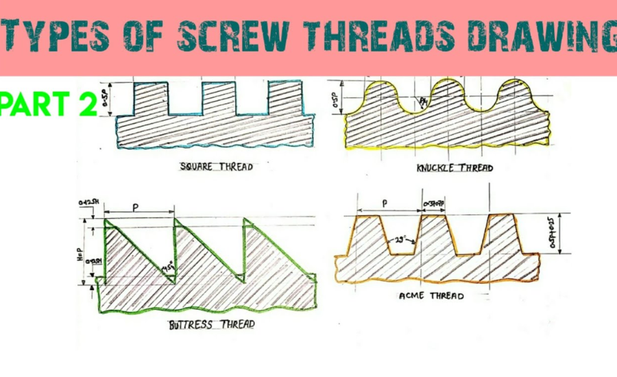
The 7/8-5 ACME thread is characterized by its unique trapezoidal shape, which sets it apart from conventional V-shaped threads, such as Unified National Coarse (UNC) and Unified National Fine (UNF) threads. This distinctive design offers several notable advantages:
- Enhanced Load-Bearing Capacity: The robust geometry of ACME threads enables them to support significantly heavier loads, making them particularly well-suited for use in various industrial machinery and equipment.
- Minimized Wear and Tear: Due to their trapezoidal structure, ACME threads experience less friction during operation, which results in reduced wear over time. This quality contributes to an extended lifespan of both the threads and the components they interact with.
- Smooth and Efficient Operation: The design of ACME threads facilitates smooth linear movement, a critical feature for applications that rely on screw-driven mechanisms, such as lifts, jacks, and precision positioning systems.
The term 7/8-5 ACME thread specifically denotes a thread with a major diameter of 7/8 inch and a thread pitch of 5 threads per inch (TPI). These dimensions are crucial for engineers, machinists, and designers who work with AutoCAD, as accurately incorporating the 7/8-5 ACME thread dimensions into their designs is vital for ensuring compatibility and functionality in mechanical assemblies.
In the following sections, we will explore these dimensions in detail, including how to effectively model and implement the 7/8-5 ACME thread in AutoCAD. Understanding these specifications will empower professionals to optimize their designs and achieve superior performance in their applications.
Designing 7/8-5 ACME Threads in AutoCAD
When it comes to designing 7/8-5 ACME threads in AutoCAD, achieving precision is paramount. Accurate thread representation is essential for ensuring that the components fit and function correctly in mechanical systems. Below is a detailed guide to creating the 7/8-5 ACME thread profile and effectively integrating it into your design:
Step 1: Create the Base Cylinder
Begin your design by constructing a cylinder with a major diameter of 0.875 inches, which corresponds to the major diameter of the ACME thread. This serves as the foundation for your threaded component and establishes the scale for the entire assembly.
Step 2: Define the Thread Profile
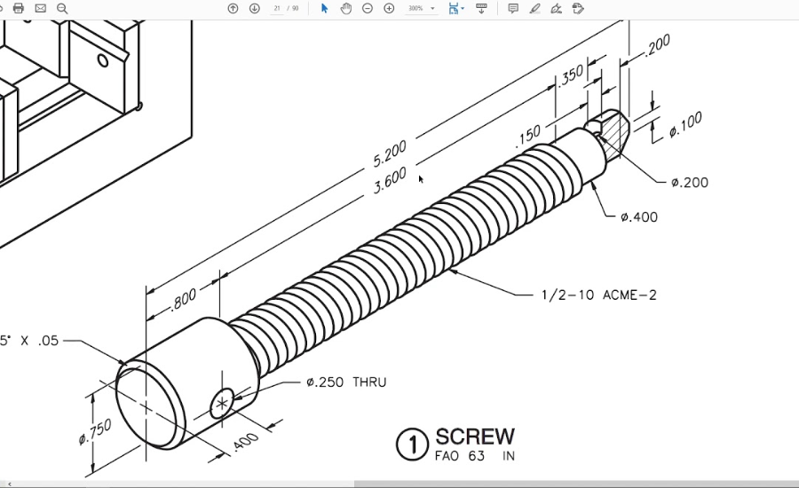
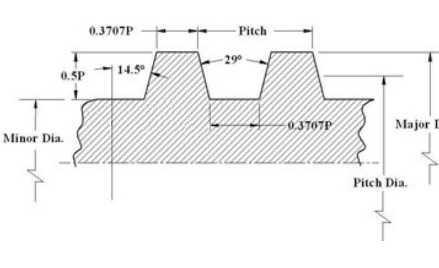
Next, use the line tool to craft a trapezoidal shape that accurately reflects the thread’s cross-section. The trapezoid should feature a 29° thread angle, a root width measuring 0.075 inches, and a crest width of 0.025 inches. Ensure the overall height of the thread is precisely 0.100 inches. This step is crucial, as the geometry of the thread significantly influences its performance and durability.
Step 3: Create a Helical Path
Utilize the Helix tool in AutoCAD to generate a helical path that will represent the spiral nature of the thread. Set the pitch to 0.200 inches to align with the specification of five threads per inch (TPI). This helix will define how the thread wraps around the cylinder, making it vital for accurate thread representation.
Step 4: Sweep the Thread Profile Along the Helix
With the trapezoidal thread profile and the helical path defined, select the Sweep tool to sweep the trapezoidal shape along the helical path. This action will produce a three-dimensional representation of the 7/8-5 ACME thread on your cylinder, allowing you to visualize how the thread will appear in practice.
Step 5: Refine and Verify the Design
Once you have created the 3D thread, take the time to review all dimensions carefully to ensure accuracy and compatibility with the mating components. Pay particular attention to critical dimensions such as the pitch diameter and minor diameter, as these factors directly affect the thread engagement and overall fit of the assembly.
Key Dimensions of the 7/8-5 ACME Thread
For engineers utilizing AutoCAD, a thorough comprehension of the dimensions associated with the 7/8-5 ACME thread is critical for precise and effective design. The following table outlines the essential dimensions that define a 7/8-5 ACME thread:
| Dimension | Value |
| Major Diameter (D) | 0.875 inches (7/8″) |
| Pitch (P) | 0.200 inches |
| Pitch Diameter (D2) | 0.8325 inches (approximately) |
| Minor Diameter (D1) | 0.755 inches (approximately) |
| Thread Height (H) | 0.100 inches |
| Thread Angle | 29° |
| Crest Width | 0.125 x Pitch (0.025″) |
| Root Width | 0.375 x Pitch (0.075″) |
These dimensions are fundamental to creating an accurate representation of the 7/8-5 ACME thread in design software and are pivotal for effective manufacturing processes.
Understanding these specifications is crucial for engineers, machinists, and designers, as precise thread dimensions ensure optimal fit and functionality in mechanical assemblies. The major diameter of 0.875 inches, combined with a thread pitch of 0.200 inches, supports significant load-bearing capabilities while minimizing wear and tear due to the efficient trapezoidal design.
In the context of AutoCAD, accurately inputting the 7/8-5 ACME thread dimensions not only facilitates the creation of detailed models but also aids in simulating real-world performance scenarios. By mastering these dimensions, professionals can enhance their designs, leading to improved operational efficiency and reliability in various industrial applications.
As we continue this exploration, we will delve deeper into the significance of each dimension and provide guidance on effectively implementing these measurements within AutoCAD for optimal results.
Detailed Specifications of the 7/8-5 ACME Thread
- Major Diameter (D)
The major diameter of a 7/8-5 ACME thread measures 0.875 inches. This dimension represents the largest diameter of the thread, which is taken across the peaks or crests. Understanding this measurement is essential for engineers and designers to ensure the compatibility of threaded components in various applications. - Pitch (P)
The pitch of the thread, which refers to the linear distance between adjacent threads, is 0.200 inches. This measurement equates to five threads per inch (TPI). Pitch is a critical dimension that influences how well the threads engage with each other, directly impacting the performance and stability of the assembly. Accurate pitch measurements are vital for the effective operation of screw-driven mechanisms. - Pitch Diameter (D2)
The pitch diameter is a crucial dimension that represents the effective diameter of the thread, measured at approximately 0.8325 inches for the 7/8-5 ACME thread. This is the diameter at which the thickness of the thread equals the space between threads. It is an essential measurement that ensures proper alignment and fit between mating parts, ultimately enhancing the assembly’s overall integrity and performance. - Minor Diameter (D1)
The minor diameter, found at the root of the thread, is roughly 0.755 inches for this thread size. This dimension is particularly important during the machining process, as it helps prevent undercutting and guarantees that the thread maintains its required strength. Proper consideration of the minor diameter ensures that the threaded connection can withstand operational stresses without failure. - Thread Height (H)
The thread height is defined as the vertical distance from the crest to the root of the thread, measuring 0.100 inches. This dimension is derived from half of the pitch and is critical for maintaining the thread’s functional profile. Accurate thread height contributes to the effectiveness of the thread engagement and the overall load distribution in applications. - Thread Angle
A notable characteristic of ACME threads is their 29° thread angle. This angle is designed to facilitate smooth engagement between threads, enhancing the assembly’s load-bearing capacity. The specific angle contributes to the efficient transfer of forces through the threaded components, ensuring reliable performance in various industrial applications.
The mastering the 7/8-5 ACME thread dimensions is essential for engineers and designers using AutoCAD. Understanding these specifications not only aids in the accurate representation of threads in design software but also ensures that mechanical assemblies achieve optimal performance and longevity. By applying these measurements correctly, professionals can enhance the functionality and reliability of their threaded designs across a range of applications.
Applications of 7/8-5 acme thread dimensions autocad
The 7/8-5 acme thread dimensions autocad is an essential component in various industries, including manufacturing, construction, and heavy machinery, due to its robust design and efficiency in load-bearing applications. Here are some of the prominent applications of this thread type:
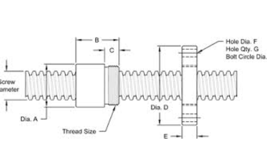
- Lead Screws: One of the most significant uses of 7/8-5 ACME threads is in lead screws, particularly in CNC (Computer Numerical Control) machines. These machines require precise linear movement for cutting and shaping materials. The trapezoidal profile of ACME threads allows for smooth motion, minimizing backlash and ensuring accurate positioning during operations.
- Jackscrews: Another critical application is in jackscrews, which are commonly employed in lifting and lowering heavy loads. These screws provide reliable mechanical advantage, making them ideal for various lifting equipment, such as hydraulic and mechanical jacks. The strength of the ACME thread design ensures that it can handle substantial weights while maintaining stability.
- Machine Tools: Many machine tools, including lathes and milling machines, utilize 7/8-5 ACME threads for their linear motion components. The durability and efficiency of ACME threads contribute to the smooth operation of these tools, allowing for high precision in machining tasks. This application is crucial for industries that demand intricate designs and fine tolerances.
- Robotic Systems: In modern robotics, 7/8-5 ACME threads are utilized in linear actuators that control the movement of robotic arms and other automated systems. The threads allow for precise control over positioning and speed, enabling robots to perform delicate tasks with accuracy.
- Construction Equipment: Heavy machinery used in construction, such as cranes and hoists, often incorporates 7/8-5 ACME threads in their lifting mechanisms. The ability to withstand high loads while ensuring smooth motion makes these threads an ideal choice for equipment designed to operate under strenuous conditions.
The versatility and reliability of 7/8-5 ACME threads make them a vital component in a wide array of applications. Their strength, durability, and precision ensure they meet the demanding requirements of various industries, ultimately enhancing operational efficiency and safety.
Related: 623-483-04 screws
Summary
The 7/8-5 acme thread dimensions autocad is a critical component in various mechanical applications, distinguished by its trapezoidal profile that offers enhanced strength and durability. With a major diameter of 0.875 inches and a pitch of 5 threads per inch, these threads are particularly suited for heavy load-bearing applications, making them ideal for use in machine tools, lead screws, and jackscrews. This guide provides a comprehensive overview of the thread’s dimensions, including the major diameter, pitch diameter, minor diameter, thread height, and angle. It also outlines the process for creating a precise 3D representation of the 7/8-5 ACME thread in AutoCAD, ensuring compatibility and functionality in mechanical assemblies. The applications of these threads span several industries, including manufacturing, construction, and robotics, underscoring their importance in enhancing operational efficiency and reliability.
FAQs
What is a 7/8-5 ACME thread?
A 7/8-5 ACME thread is a standardized thread type characterized by a major diameter of 0.875 inches and a pitch of 5 threads per inch (TPI). Its trapezoidal shape provides improved strength and reduced wear, making it ideal for heavy-duty applications.
What are the advantages of using ACME threads?
ACME threads offer several advantages, including enhanced load-bearing capacity, reduced friction and wear, and smooth linear movement. These qualities make them suitable for applications such as lead screws, jackscrews, and various machine tools.
In what industries are 7/8-5 ACME threads commonly used?
7/8-5 ACME threads are widely used in industries such as manufacturing, construction, and robotics. They are crucial in applications involving machine tools, lifting equipment, CNC machines, and robotic systems due to their strength and reliability.
Why is it important to use accurate thread dimensions?
Accurate thread dimensions are critical for ensuring compatibility and functionality within mechanical assemblies. Deviations from specified dimensions can lead to performance issues, improper fit, or failures in the field, affecting the overall efficiency of the equipment.
What tools in AutoCAD are necessary for creating ACME threads?
Key tools in AutoCAD for creating ACME threads include the LINE tool for drawing the thread profile, the Helix tool for creating the helical path, and the Sweep tool for generating the 3D thread representation. Additionally, dimensioning tools like DIMLINEAR are essential for annotating measurements.
or more in-depth articles, visit our blog today!